Comparison of Digital Fiber DAS and Analog Fiber DAS
With the development of RF digital technology, Digital Fiber Distributed Antenna System (DAS) has been launched on the market. The technical advantages between the traditional analog fiber remote system and digital fiber remote system have been a controversial topic. I will discuss the differences between these two technologies from the technical perspective.
Technical Principles Overview
Both the Digital Fiber DAS and the Analog Fiber DAS are a two-tier architecture consisting of Optical Master Unit (OMU) and Optical Remote Units (ORUs).
Traditional RF over fiber uses analog RF and fiber-optic (FO) transceivers. The RF modulates the light, and vice versa.
In the Analog Fiber DAS, the RF from the analog RF transceivers directly modulates the light inside the fiber via ROF (Radio Over Fiber) Module inside OMU. At the other end, the light will be restored to the RF signal output through the ROF module inside ORU. This kind of direct analog amplitude modulation method will attenuate the RF signal level as the energy of the optical signal decreases as it travels. 1 dB optical loss = 2 dB RF loss.
A Digital Fiber DAS (Distributed Antenna System) converts the RF analog signal to digital. Then, one the fiber-optic cable, only digits 1 and 0 are transmitted.
However, in the Digital Fiber DAS, the RF signal is converted into digital CPRI data stream by ADC (Analog-to-digital Converter) and FPGA inside OMU (Optical Master Unit), and the high-speed digital CPRI packet data is transported via single mode fiber, multimode fiber, and received by the ORU (Optical Remote Unit) from the SFP+ (Enhanced Small Form-factor Pluggable) digital optical fiber transceiver, the ORU receives the master digital optical signal through the SFP+ and convert the digital CPRI packet data stream back to RF by DAC (Digital-to-analog Converter), and amplify the signal for delivery to the antennas. On the reverse path (Uplink), the ORU and OMU perform the inverse functions and delivery the signal back to the corresponding off-air antenna, BDAs or Base Stations. Since the technology of the Digital Fiber DAS is digital CPRI data stream transmission, there is no energy loss in the whole transmission process that the output and input signal can be consistent.
Difference in Network Topology & Noise Floor
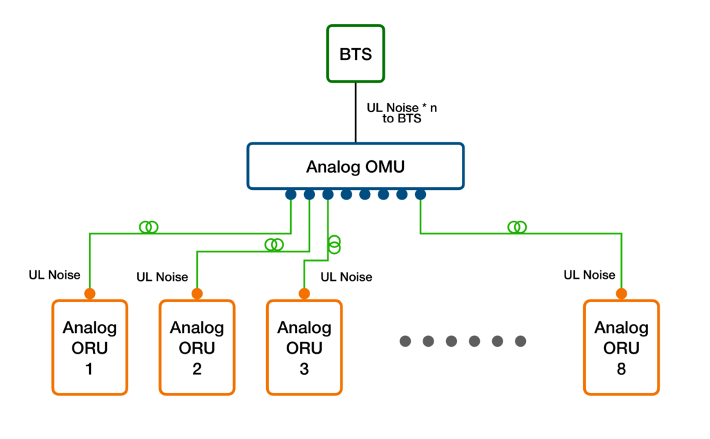
Traditional Analog Fiber DAS can only adopt star topology due to the limitation of Dynamic Range (DR*) and Superimposition on Uplink Noise. Therefore, for chain coverage scenarios such as long tunnels, it will have to be requested to repeatedly deploy optical cables, which wastes optical fiber resources.
*DR Limitation: 3dB optical loss is generated every two halves of the optical signal, which will also cause 6dB RF dynamic loss; therefore, as the attenuation of the optical signal increases, the DR (Dynamic Range) on Uplink Noise drops rapidly.
Generally, the noise figure of a ROF (Radio Over Fiber) module is -40dB, so the uplink noise floor of a pair of ROF modules (OMU + ORU) is -134dBm/Hz, considering the gain fluctuation +/-3dB, so the actual uplink noise floor should be -131~-137dBm/Hz, that is, a pair of ROF modules will introduce the minimum noise floor NROF to the uplink of whole system as -137dBm/Hz.
Taking the LTE system as an example, the inherent noise figure of each RB of the base station NeNB_RBis:
-174dBm/Hz+5dB*+10LOG (15000Hz*12) =-116.4dBm/RB
Where, 5dB is the Noise Figure of eNB.
The uplink noise floor NROF_RB of each RB reached the base station by a pair of ROF modules is:
-137dBm/Hz – 42dB*+10LOG(15000Hz*12)=-126.4dBm/RB
Where, 42dB is the total signal loss by attenuator and jumper cable from eNB to OMU.
It can be calculated from the above formula that, in order to ensure that the uplink noise figures coming from the total Fiber DAS system does not affect the base station, without considering other power factors, the uplink noise figure with the n * ROF modules connected to the base station should be less than NeNB_RB:
Therefore, the maximum number N of ORUs are 10 units according to above formula.
If the uplink receiving sensitivity is allowed to be sacrificed in indoor coverage, and the receiving noise floor of the base station allows to be raised by 3 dB, the maximum number of ORUs connected by star topology can be increased to 20 units.
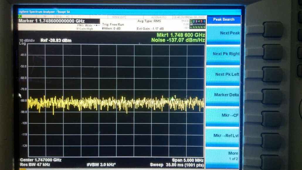
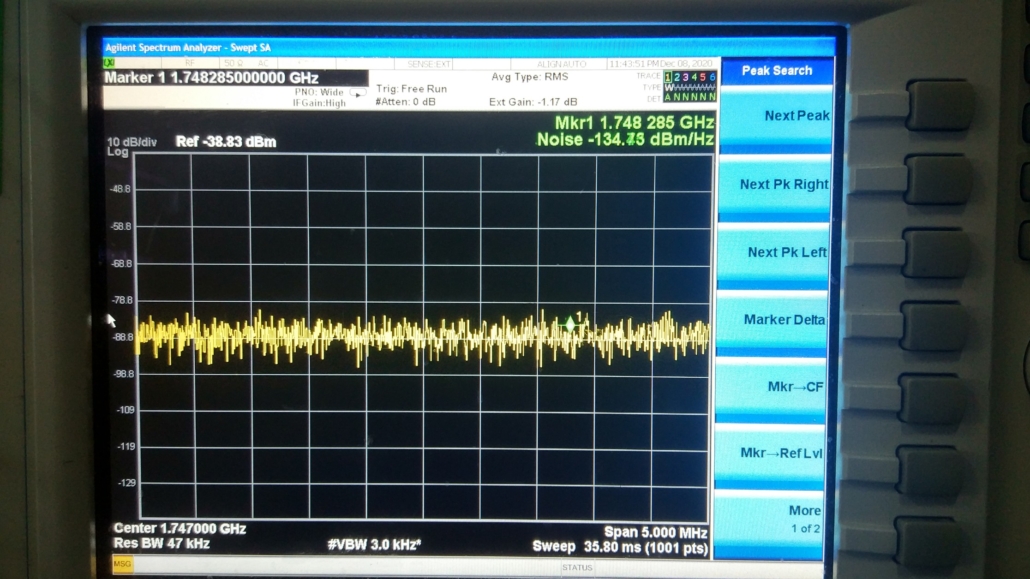
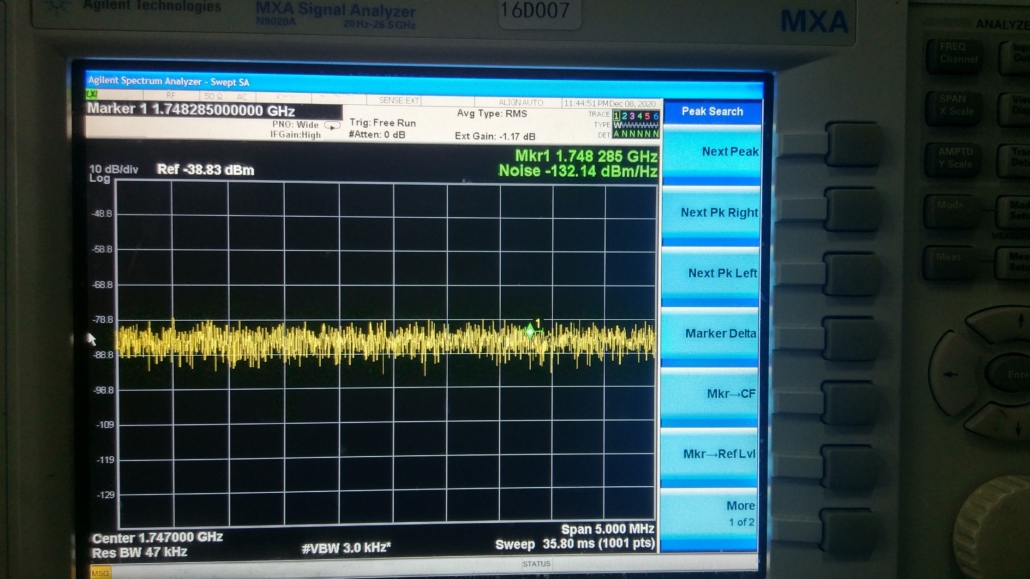
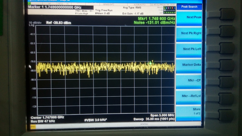
The following figures show the actual simulation lab test of various uplink noise of Band3 Analog Fiber DAS with One OMU is connected respectively to various ROF modules as one, two, three and four ORUs, the simulation lab test results clearly show the superposition of the system’s uplink noise figure increases linearly.
1+1: -137.07dBm
1+2: -134.15dBm
1+3: -132.14dBm
1+4: -131.01dBm
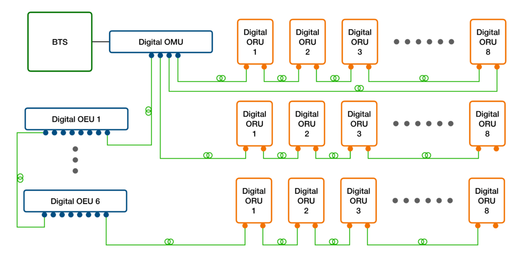
Compared to Analog Fiber DAS, the Digital Fiber DAS has no noise superimposition problem, and the signal can be regenerated multiple times. It supports cascading deployment of ORUs. It can be flexibly used in star, daisy, and other networking topologies, and can be adapted to various complex scenarios as above figure shown.
A cascade connection can be used between the ORUs to save fiber resources. Generally, a Digital OMU has at least 4 SFP+ interfaces. When deployed in a cascade connection, a maximum of 4*8=32 ORUs can be connected.
If an Optic Expansion Unit (OEU) is used, each SFP+ interface still can be cascaded with 6 OEUs by fiber cable, each OEU can be connected to 8 ORUs, and the maximum can reach 4*6*8=192 ORUs.
The Digital Fiber DAS usually has uplink noise suppression feature, so the noise floor is mainly coming from the phase noise generated by the uplink DAC in OMU.
Actually, the below figure show RF test result for the Noise Floor at the uplink RF output port of the OMU of Band3 Digital Fiber DAS. The noise floor NROD we obtained is -145.32dBm/Hz.
The uplink noise floor NROD_RB of each RB reaches the BTS coming from Digital Fiber DAS is:
-145.32dBm/Hz-42dB*+10LOG(15000Hz*12)=-134.72dBm/RB
Where, 42dB is the total signal loss by attenuator and jumper cable from eNB to OMU.
Obviously, this value is much lower than the noise floor NeNB_RB of the base station as -116.4dBm/RB above mentioned.
Optic Delay Aligning & Compensate
Traditionally, there is no optic delay aligning feature between the remote sites (ORUs) of Traditional Fiber DAS, which cannot compensate for the delays between the ORUs, and cannot suppress multipath interference, resulting in multipath interference exists in the overlapping area of ORUs coverage.
It means that the optical delay compensation has to be done by using the same length of fiber to all remote ORUs, or manually calculating the delay and adding delay elements to synchronize transmission from the OMU to the remote ORUs.
With an all-digital and software-configurable platform, the Digital Fiber DAS can align the time delay automatically or manually to eliminate the interference between various coverage areas.
- Real-time automatic measure the optical delay between OMU and each ORU.
- Automatically or manually aligning & compensate the delay between the OMU and each ORU to make the delay equal.
- Eliminate multipath interference caused by different delays in overlapping coverage areas between different ORU remote ends in the same sector.
RF Input Dynamic Range influenced by Fiber Length
The transmission distance of the traditional Fiber DAS is affected by the length of the fiber cable. As the length of the fiber cable increases, the energy of the optical signal in the transmission will decrease and the RF will be reduced, 1 dB optical loss = 2dB RF loss. Therefore, input signals beyond a certain distance, signal-to-noise ratio will deteriorate and cannot meet the requirements of the system.
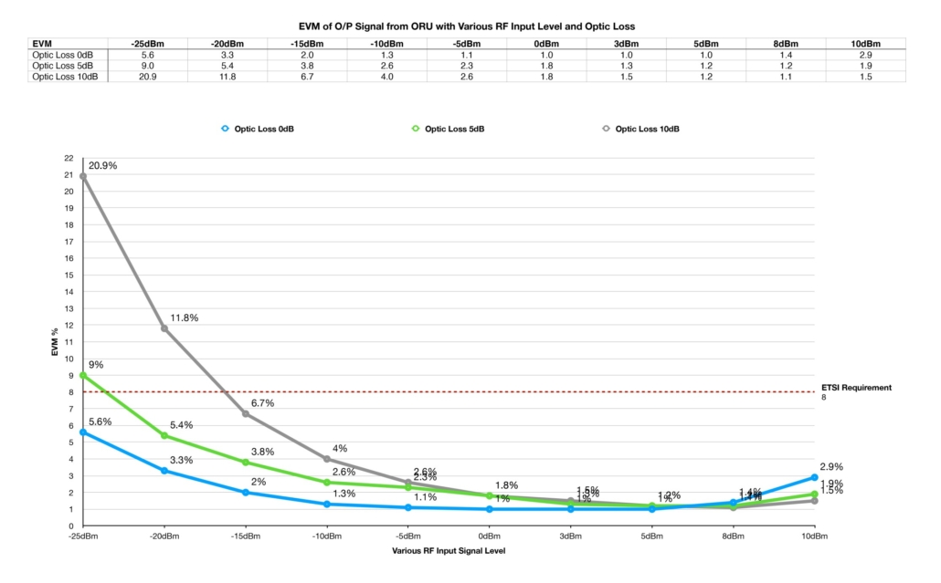
The following is the laboratory simulation verification test result. The signal source is LTE BAND3 Signal Generator to simulate BTS, with the configuration as channel bandwidth 20MHz and 64QAM modulation, and the OMU and ORU are directly connected with an optical cable. 5dB and 10dB optical attenuators are added between the OMU and ORU to simulate different transmission distances. At the same time, when set Signal Generator with different RF level of 20MHz LTE Band3 downlink signals to simulate different input signals at different distances to OMU and test the EVM and ACPR of the output signal of the remote ORU as below.
Through the above EVM test, to ensure that the LTE requirement EVM<8%, the input dynamic range of the Analog Fiber DAS should be between -15 and +10 dBm.
[/av_textblock]
[av_image src='https://heliostechnologies.asia/wp-content/uploads/2021/07/1613805059834-1030x719.jpeg' attachment='406' attachment_size='large' copyright='' caption='' styling='' align='center' font_size='' overlay_opacity='0.4' overlay_color='#000000' overlay_text_color='#ffffff' animation='no-animation' hover='' appearance='' lazy_loading='disabled' link='' target='' title_attr='' alt_attr='' id='' custom_class='' av_element_hidden_in_editor='0' av_uid='av-krariz7a' admin_preview_bg=''][/av_image]
[av_textblock size='' av-medium-font-size='' av-small-font-size='' av-mini-font-size='' font_color='' color='' id='' custom_class='' av_uid='av-krarjdgi' admin_preview_bg='']
It is obvious from above ACPR test, that the optical attenuation caused by the different input signal through different fiber length will attenuate the RF signal in the light transmission, which resulting in ACPR deterioration that cannot meet the requirements of the LTE system. In the short distance and the light attenuation is very small, such as indoor coverage scenario typically, the light attenuation <1dB can be almost neglected, and the valid input RF level range to the Analog Fiber DAS should be -15dBm~+5dBm with the ACPR >40dBc guaranteed as above figure shown. In the same way, when the light attenuation is 5dB, valid range of input RF level to the Analog Fiber DAS is -5dBm~+8dBm; when the optical attenuation is 10dB, valid range of input RF level to the Analog Fiber DAS is 0dBm~+10dBm. Therefore, to ensure that ACPR meets > 40dBc, the dynamic range of input RF level to the Analog Fiber DAS within 10Km transmission distance should be -5~+5dBm.
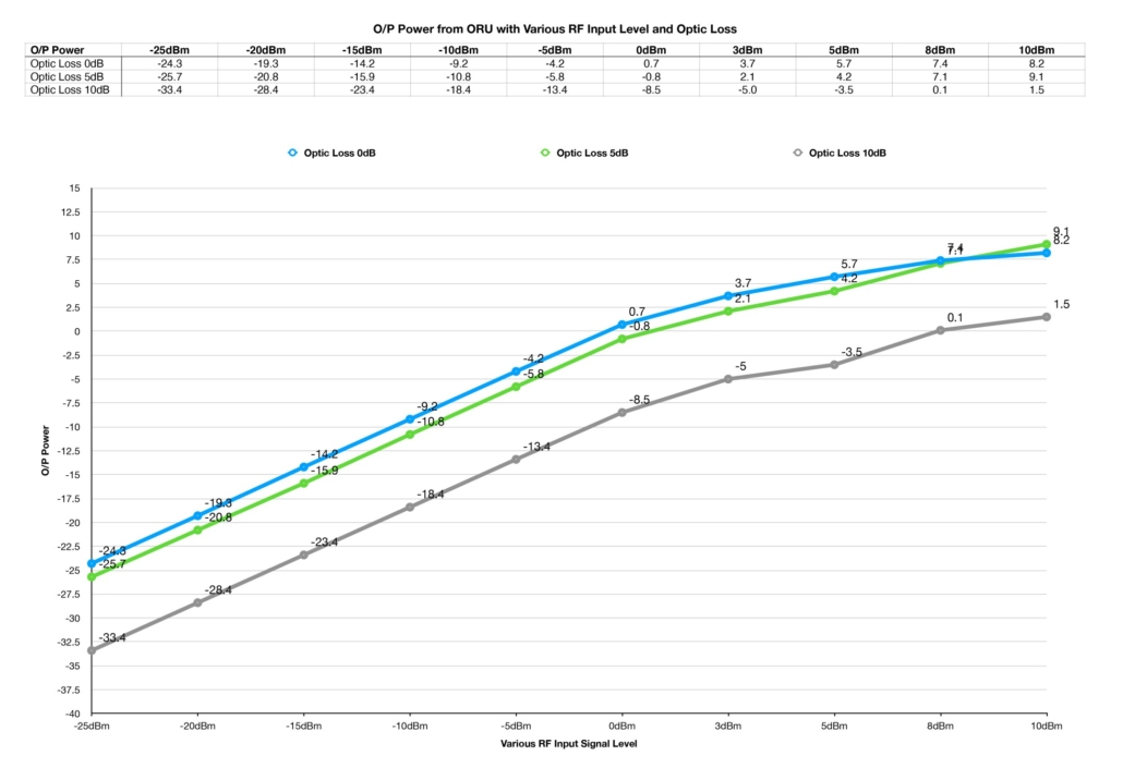
From above figures, we can see that the overall output power from ROF (ORU) keep linearity between input RF level -25dBm to +5dBm, then shows nonlinear after the input RF level over +8dBm.
Based on the analysis of all the above factors, in order to ensure the performance of LTE system, for Analog Fiber DAS, the transmission distance is recommended to be less than 10km and the input RF level should be -5 ~ +5dBm.
Digital Fiber DAS
A Digital Fiber DAS (Distributed Antenna System) converts the RF analog signal to digital. Then, one the fiber-optic cable, only digits 1 and 0 are transmitted to remote ORU, so the signal will not attenuate with the attenuation of light signal and keep dynamic range and unchanged services in long-distance and multi-link transmission system, which makes the network design more flexible.
It can be seen from the above EVM & ACPR & O/P Power test result that the Digital Fiber DAS can guarantee the linear output at RF input signal level -25~+10dBm, and the digital ALC accurately controls the output level of 0dbm. The signal will not be affected by the fiber length in the transmission process, and EVM and ACPR will not deteriorate.
RF Bandwidth, Channelization and Ripple in Band
The ROF module of Traditional Fiber DAS can only support up to 80MHz ~ 3.0GHz, and usually uses SAW filter to filter out different band signals and amplify them. The fluctuation is large, and the out of band rejection is small, the energy between channels/sub-bands are unbalanced, it will be very easy to cause inter interference in multi-band/multi-technologies/multi-operator system.
The RF bandwidth of Digital Fiber DAS depends on the frequency bandwidth of ADC / DAC and the transmission rate of SFP interface. With digital filtering technology, the out of band rejection is better, and different channel equalization compensation is supported in the same frequency band to ensure all channel energy balance, and the fluctuation between channels is less than 2dB, which is better than the Traditional Fiber DAS. Since each band adopts independent ADC / DAC design, there is no mutual interference between sub-systems.
Conclusion
In summary, through the above technical analysis, it can be concluded that the Digital Fiber DAS is superior on technology to the Analog Fiber DAS, with wide input dynamic range and network expandable according to the needs.
Helios® Multi-Band Digital Optical Transport System (M-DOTS™) is the most flexible, scalable and complete solution for addressing coverage and capacity needs for cellular and public safety wireless network. The M-DOTS™ improves wireless network coverage and capacity by extending services from existing cell sites, to hard-to-reach areas by digital CPRI distributing coverage from a centralized radio suite.
Utilizing a centralized digital CPRI distributed architecture, Helios® M-DOTS™ is a two-tier architecture consisting of the Optical Master Units (OMUs) and Optical Remote Units (ORUs). RF signals from Base Stations, off-air, BDAs or combination thereof can be received. In the case of off-air feed, the OMU has the option to combine the functions of the off-air Repeater and OMU to provide transmission and distribution of radio signals. The signal is filtered and then converted to a digital CPRI data stream. The digital CPRI packet data stream is transported via single mode fiber and received by the ORUs. The ORUs then convert the digital CPRI packet data stream back to RF and amplify the signal for delivery to the antennas. On the reverse path (uplink), the ORUs and OMU perform the inverse functions and delivery the signals back to the corresponding off-air antenna, BDAs or Base Stations.
The all-digital platform with ultra-wide bandwidth RF front-end design and modular architecture enables multiple band/technologies/operator and network topologies including star, chain and hybrid to cater to different deployment scenarios. These network topologies provide reduced fiber plant usage and installation cost, and effective fiber loop redundancy configurations.
The M-DOTS™ flexibility and scalability offers service provider an optimal solution for multiple applications, such as dense urban centers, dense suburban areas, campuses, enterprise buildings, subways and tunnels. The M-DOTS™ digital CPRI distributed architecture and small form factor allow service providers to cost-effectively increase coverage and capacity in these hard-to-reach areas.
With ultra-wide bandwidth RF front-end design enables M-DOTS™ supports up to six RF bands. All each RF band can be configurated to be FDD or TDD mode in factory and supports up to 100MHz bandwidth RF signals in order to be capable of simulcasting signals for multiple bands/technologies/operators and MIMO, even ultra-wide bandwidth requirement for future 5G NR TDD.
Each M-DOTS™ OMU has four 10Gbps SFP+ digital optic ports and supports up to 32 ORUs by star, chain, ring and hybrid network topologies, even up to 196 ORUs by adding OEUs in some scenarios, such as subways and tunnels.
Of course, in some unimportant scenarios or budget limits, there still can also select HELIOS® Traditional Analog Fiber DAS, but just need to carefully design the coverage system based on characteristics of Analog Fiber DAS, which can also meet the signal coverage requirements.
To learn more about our Digital CPRI Fiber DAS solution, please refer to https://www.heliostelecom.com/digital-cpri-optical-transport-system/ or contact us info@heliostelecom.com .

